Background
jLogo Programming
- Commanding a Turtle
- Pseudocode
- Adding New Commands
- Iteration & Animation
- Hierarchical Structure
- Procedure Inputs
- Operators & Expressions
- Defining Operators
- Words & Sentences
- User Interface Events
- What If? (Predicates)
- Recursion
- Local Variables
- Global Variables
- Word/Sentence Iteration
- Mastermind Project
- Turtles As Actors
- Arrays
- File Input/Output
- AI: Pitcher Problem Solver
Java
- A Java Program
- What's a Class?
- Extending Existing Classes
- Types
- Turtle Graphics
- Control Flow
- User Interface Events
Appendices
- Jargon
- What Is TG?
- TG Directives
- jLogo Primitives
- TG Editor
- Java Tables
- Example Programs
- *** New ***:
Installation Notes
Updates
- December 13, 2008
- January 6, 2012
- March 15, 2013
- January 20, 2014
- February 13, 2014
- July 29, 2014
- January 18, 2016
- January 29, 2016
- August 19, 2016
Lastly
What If? (Predicates)
"When you come to a fork in the road take it."
- Yogi Berra
Introduction
So far, when the programs we've written get performed, all of the instructions that make up our programs get performed.
Think about how the Logo interpreter in TG performs your programs. It reads your program line by line. Each line must be either a directive or an instruction.
The interpreter does not see most of the directives - they help you (the programmer) edit and test your code. But one, the TO directive is special. All of the lines in the program after it up to and including its matching END directive line are not performed. Instead, the lines between the TO and END lines are remembered and associated with a name supplied as an input for the TO directive. This is called a user-defined procedure definition, which we learned about in the Adding New Commands lesson.
Instruction lines not surrounded by "TO" and "END" lines are performed one after, another down the program text, by the interpreter. There are some side trips it can take. When the interpreter performs a REPEAT command, it performs a list of instructions, provided as an input, some number of times. When an instruction to be performed is a procedure invocation, to some procedure that you wrote, the interpreter recalls the procedure's definition and performs its instructions. Once this is done, the interpreter picks up where it left off, at the spot in your program immediately following the procedure invocation.
The point I'm making is that all of the instructions in your program get interpreted and performed. What if you only want some instructions to be performed when some condition exists? As an example, what if we want to do something only when an up-arrow key is pressed and something else when the down-arrow key is pressed?
In this lesson, you will learn about
- a new kind of thing called a boolean value, which can have two values: the symbol true or the symbol false
- predicates - boolean operators, procedures which output either a true or false value
- the IF command which expects two inputs, a predicate and a list of instructions. The list of instructions is only executed if the predicate outputs a true value.
Boolean Values
In this lesson, you will want your program to do some things only when certain conditions are true. This means you will need to use the data type: boolean. Boolean data can have different values, but only two: true or false. Each of these values is represented by a word, so you can express them in your programs as "true and "false.
Boolean values are used in computer programs to control what the program does.
Let's look at a few primitive (built-in) operators that Logo has and some examples of how you can use them.
Predicates - Operators Which Output Boolean Values
      predicate n. 1 a: something that is affirmed or
      denied of the subject in a proposition of logic
      b: a term designating a property or relation

                - Webster's New Collegiate Dictionary
So, in other words, a predicate is something that is either true or false - the boolean values. In Logo, predicates are operators, procedures (both built-in and used-defined) that output a boolean value. Table 12.1 shows the first three built-in predicates you'll need/use.
| Name | Input(s) | Description |
| EQUAL? EQUALP |
value1 value2 | Outputs "true if value1 is equal to value2, "false otherwise. |
| GREATER? GREATERP |
number1 number2 | Outputs "true if number1 is greater than number2, "false otherwise. |
| LESS? LESSP |
number1 number2 | Outputs "true if number1 is less than number2, "false otherwise. |
| |
||
Figure 12.1 shows some example output values for these operators.
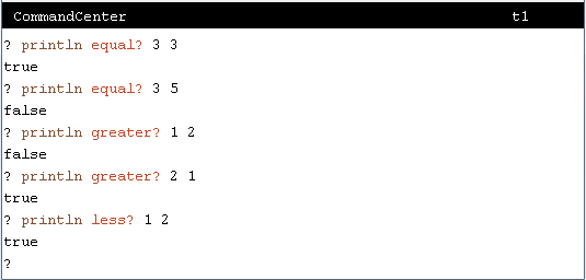 Figure 12.1
Figure 12.2 shows a few more example output values for these operators when used with symbolic values, words in this case. Notice that equal? works correctly, but that less? causes an error. You cannot compare symbolic values in Logo for magnitude difference. greater? and less? can only have numbers for their inputs.
 Figure 12.2
IF - Maybe Execute a List of Instructions
So, how do we use these boolean operators in our programs?
Logo has a way of interpreting a list of instructions only when a specified condition is true. The syntax of the if command is:
| if | <predicate> | <List-of-Instructions> |
- the command name: "if"
- a <predicate>, and
- a <List-of-Instructions>
<predicate> can be the word "true, the word "false, or a procedure invocation of an operator that outputs either "true or "false.
The syntax of a <List-of-Instructions> is:
| [ | <Instructions> | ] |
- an open square bracket,
- <Instructions>, and
- a close square bracket
Here are a couple of examples of the IF command in action.
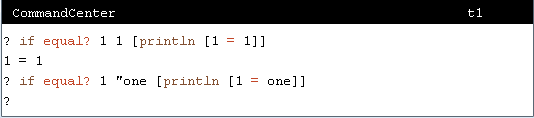 Figure 12.3
If you have the TG programming environment on your computer, use it to experiment with these new boolean opeators and the IF command. Otherwise, here is the TG applet. Use it to try stuff out.
TG Programming Environment Applet
Additional Boolean Operators
You can do quite a lot with EQUAL?, GREATER?, and LESS? operators. But, there are times when you only want to do something when multiple boolean operators are all true or false. And complementary to this, there are times when you want to do something when any one of multiple boolean operators is true or false.
Table 12.2 introduces boolean operators which provide these needed capabilities.
| Name | Input(s) | Description |
| AND | trueFalse1 trueFalse2 | Outputs true if both trueFalse1 AND trueFalse2 are true, false otherwise. |
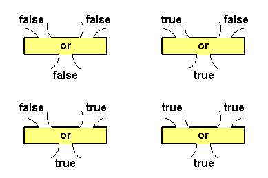
| OR | trueFalse1 trueFalse2 | Outputs true if trueFalse1 OR trueFalse2 is true, false otherwise. |
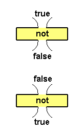
| NOT | trueFalse | Outputs false if trueFalse is true, else true when trueFalse is false. NOT outputs the opposite boolean value of its input. |
| |
||
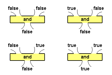
Figure 12.4 shows plumbing diagrams for all possible inputs and the resulting output for the AND operator.
 |
| |
Figure 12.5 shows plumbing diagrams for all possible inputs and the resulting output for the OR operator.
 |
| |
Figure 12.6 shows plumbing diagrams for all possible inputs and the resulting output for the NOT operator.
 |
| |
Time for a project that will demonstrate the importance of these operators.
Project: MousedQuadrants
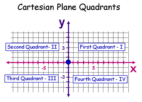
We are going to write a program which draws X and Y axes, visualizing a Cartesian plane. When the mouse is clicked in the graphics canvas, the program will print the name of the quadrant the mouse was in when it was clicked. As an example, if the mouse is clicked above the X axis and to the right of the Y axis, the program will print "Quadrant I" in the CommandCenter.
Figure 12.7 is an illustration of the Cartesian plane quadrants (from Passy's World of Mathematics).
 |
Here's a link to most of the program; it is missing the body of the mouseClicked procedure. If you have TG on your computer system, copy/paste it into its Editor and save it to a file named MousedQuadrants.jlogo.
If you do not have TG but are using a browser that supports Java applets, ...
- Go back up to the TG applet,
- if the graphics canvas window is not open, choose the Window->Canvas-> Open menu item,
- choose the File->New menu item,
- enter loadcode MousedQuadrants_0.jlogo in the CommandCenter.
Fill in the body of the empty mouseClicked procedure with code that prints a quadrant label when the mouse is clicked in the graphics canvas.
Play around a bit. When you have the program working, or need help, click here.
Grid Toolkit Paint Program Bug
At the end of the last lesson we were playing around, using the Grid Toolkit to write a simple cell painting program. In the process, we found that there was a bug in our program and we did not know how to fix it. When the mouse was clicked outside the grid, the program created a new cell at the point of the click.
What the program needs to do is verify that the mouse X and Y coordinates are within the bounds of the grid. It should only fill a cell if this is true. And now that we have the IF command we can fix the bug. Let's extend the Grid Toolkit with two new boolean operators which perform the appropriate testing. Here is pseudocode for what one of the operators (gridContainsPos?) needs to do.
|
But just try to draw a plumbing diagram for that pseudocode. Luckily for us, there is a simpler implementation of a gridContainsPos? operator. All we need to do is make four simple comparisons to see if the point is outside the rectangle.
- is the point above the grid,
- is the point below the grid,
- is the point to the left of the grid, or
- is the point to the right of the grid
If any of these comparisons return the word "true then gridContainsPos? outputs "false. If all of these comparisons fail (if they all output "false), then gridContainsPos? outputs "true. Here are the new gridContains..? operators.
|
Notice that they only output either the word "true or the word "false. They are boolean operators. And we make this obvious by ending their names with a question mark (?).
Given these operators, I've changed the mouseClicked procedures in my cell painting program. I wrote a few versions, two for each flavor of mouseClicked. All but one of these mouseClicked procedures are commented out. But, they all do the job. Here they are.
|
All I had to do was invoke gridContainsXY? or gridContainsPos? with the proper input(s). Since both return either true or false, they can be used as the first input to IF. By surrounding the existing instruction that fills a cell with square brackets, it becomes the second input to IF. Bug fixed!
Project: Moving the Turtle Around the Grid
Similarly with mouse clicks having an X and Y pair of coordinates (the location of the mouse when it is clicked), the turtle has a current location. You saw one way to get this location information a couple of lessons ago when I introduced the POS operator. Table 12.3 has its description again along with two additional operators which also provide access to the turtle's current location.
| Name | Description | |
| POS | Outputs the current coordinates of the turtle as a sentence. The X coordinate is the FIRST of the sentence; the Y coordinate is the LAST of the sentence. | |
| XCOR | Outputs the turtle's X-coordinate. | |
| YCOR | Outputs the turtle's Y-coordinate. | |
| |
||
With these operators and our new grid toolkit, we are going to write a program: TurtleInGridLand. How you want to work on the project is up to you. I'll give you three choices.
-
- Copy your Grid Toolkit code to a file named TurtleInGridLand.jlogo
- Copy/Paste the following code onto the end of this program.
to green output 2 end ; keyPressed key values to downArrowKey output 65537 end to leftArrowKey output 65538 end to rightArrowKey output 65539 end to upArrowKey output 65536 end ;respond to a key pressed event - move/rotate the turtle to keyPressed :keyNum if equal? :keyNum upArrowKey [forward gridCellSize] if equal? :keyNum leftArrowKey [left 90] if equal? :keyNum rightArrowKey [right 90] if equal? :keyNum downArrowKey [back gridCellSize] end to main hideturtle home clean gridPaint gridGotoCellCtr random gridNumCells setheading 0 repeat (random 4) [right 90] setpencolor green showturtle penup end main - Change the gridNumCol procedure so that it outputs 12 instead of 8.
- Change the gridNumRow procedure so that it outputs 8 instead of 5.
- Start TG,
- choose the File->New menu item,
- Here is my first version of TurtleInGridLand.jlogo. Copy/paste my code into TG's Editor,
- and use File->Save As... to write your new program out as the file TurtleInGridLand.jlogo
- Go back up to the TG applet,
- choose the Window->Canvas->Open menu item,
- choose the File->New menu item,
- enter loadcode TurtleInGridLand_0.jlogo into the CommandCenter.
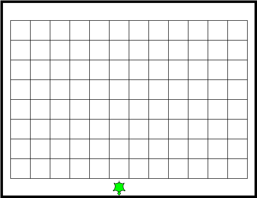
When you run this program you should end up with something in the graphics canvas that looks like Figure 12.8.
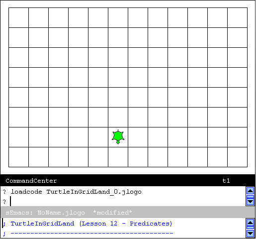 |
The turtle should appear in a random cell location and facing in a random direction. If your curious about how I did the random stuff, checkout the main procedure.
Click the left mouse button in the graphics canvas so that it has the keyboard focus, its perimeter turns black.
Move the turtle around with the arrow keys. The up-arrow key should move the turtle forward one cell. The left-arrow and right-arrow keys should rotate the turtle left 90-degrees and right 90-degrees respectively. The down-arrow key should move the backward one cell.
Read the keyPressed procedure... That's where the IF command, the main topic of this lesson, comes into play. As explained in the previous lesson, when a user presses down on a keyboard key, a key-pressed event occurs and the keyPressed procedure is invoked with its :keyNum input containing a numeric representation of which key. In our little program, what it does, what happens, depends upon the value in the input :keyNum. The contents of :keyNum is compared with the outputs of procedures leftArrowKey, rightArrowKey, downArrowKey, and upArrowKey which act as symbolic constants. Take some time to understand what is happening, how this works.
The program has a bug in it. Did you find it? As shown in Figure 12.9, you can move the turtle out of the grid!
 |
Fixing this bug is your new challenge. Write two procedures which move the turtle forward and backward. moveForwardCell should move the turtle forward one cell if, and only if, it will still be within the bounds of the grid. moveBackwardCell should work similarly, but back the turtle up.
Think about how we just solved a similar bug in the Grid Toolkit cell painting program. We used our new boolean in-grid operators. But in the cell painting program we worked with the coordinates of a mouse-click. To fix this bug, you need to work with the turtle's location, its coordinates.
Here is the skeleton of what I'm asking you to do.
|
If you are stuck, remember the steps to take in programming. Think about what you know how to do. Use TG's CommandCenter to experiment with the new operators. Enjoy the challenge of this puzzle.
When you have the program working, or are at wits' end and need help, click here.
Project: A User Interface
Now that we have the IF command in our bag of tricks, we can start to do stuff that you see computer programs doing all the time. Let's start with a simple user interface that we can later extend into the Mastermind game. What I think will surprise you is how much code is involved.
Figure 12.10 shows the desired user interface for this project.
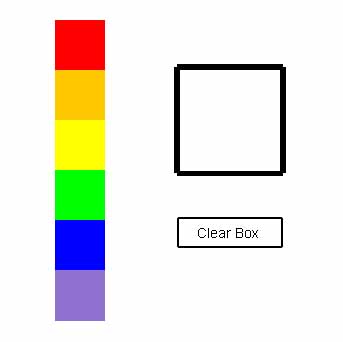 |
The user interface consists of a line of color choice boxes (six colored squares), a big empty box, and a "Clear Box" button (a rectangle with a label in it). The first thing our program needs to do, in the main procedure, is draw all of these things. Doing stuff like this is commonly called initialization of the program.
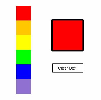
The program then waits for mouseClicked events. When the mouse is clicked in one of the color choice boxes, the program fills in the big box with the color that was clicked on. Figure 12.11 shows what happens when the mouse is clicked in the red color choice box.
 |
A User Interface: Program Design
Another way of looking at this program is to think of it as a group of objects which interact with each other. There is
- a big box that is initially empty (white) but, like a chameleon, changes color when asked to,
- a line of colored squares (color choice boxes) which do something when they are clicked on. When the mouse is clicked on one of the colored choice boxes, it tells the big box to change its color, and
- a button that, when clicked on, tells the big box to empty itself, to clear out any color it contains.
Think of the program as some kind of a machine, one with little people in it.
The big box person knows how to repaint itself with a color when requested.
The color choice boxes people know their locations on the graphics canvas. Their lower-left corners and size are available as symbolic constants. When they are told that the mouse was clicked while it was within the line of them, they know how to figure out which one was clicked on. Since they can communicate with big box, they tell big box to change, to repaint itself with the clicked-on color.
The clear button person's job is easy. When it is told that the mouse was clicked within its boundaries, it simply tells big box to paint itself white. White is just another color.
The final person's job is to pay attention to the mouse. It handles mouse clicked events. When it receives one, it checks to see if the mouse was clicked on its friends, color choices and clear button. If so, it tells one of its friends to do whatever they are supposed to do when the mouse is clicked on them.
So, given this description of how the program works, take a little time to think about how you would write a program that embodies these little people. If it helps, get some paper and a pencil and sketch out a picture of the program.
Start up TG and use File -> New... to get going with this new program; for a file name, I suggest MastermindUI.jlogo.
Moving On to Writing the Program
At this point, if you want to write the program completely on your own, go for it! You will learn the most this way. Why? Because programs can be written so many ways. When you are done or seem to be hung-up at some point, read what follows. What follows is sort-of a thought process of a virtual experienced programmer writing the program. It is one way, but not the only way, to write the program.
I always like to get something very simple working, and then build on it. So, the obvious first thing to do is paint/draw what the program looks like when it starts up. In this case, Figure 12.10 shows what we want. There is nothing in this figure that we do not know how to do. We need to paint the line of color choice boxes, an empty big box, and what is called a button in graphical user interface terminology. Drawing a button is simply drawing a rectangle with a label in it.
But, before I start writing a bunch of instructions, telling the turtle to draw this and that, I want to define some symbolic constants. The first symbolic constants I'll type in are the colors and turtle headings I will need. Then I'll define where different objects are on the graphics canvas. This gets me both flexibility and readability and extends the vocabulary my program is composed from. Good names for things help us write an easy-to-read and understand program.
I'm going to name the line of color choice boxes colorChoices. This choice of naming comes from my little people description above. Everything that has anything to do with the line of color choice boxes will have "choice" in its name. So, first I defined a few new procedures which can be used to draw the line of boxes.
|
Before you read on, take a bit of time to try to guess why I defined each of them. What will each of these symbolic constants be used for?
What I was doing while I was defining the colorChoice symbolic constants was thinking about how I would draw the strip of colors. I was thinking... "first I'll use penup and setxy to position the turtle at the middle of the top of the strip." Continuing, "then I'll set the turtle's heading to south, its pen size to colorChoiceSize, its pen color to red, lower the pen and then use the forward and setpencolor commands to draw the boxes, one color at a time."
But, I kept thinking ahead... "I'm going to need to know where one color ends and a different color starts - so that I can determine which color the mouse was clicked on." With this in mind, I switched my plan and defined a symbolic constant for the bottom Y coordinate of each color. These can be used with sety commands to draw the strip - AND - I will be able to use them to determine which color is clicked on, when I get to writing that code.
Just a side question for you - do you know why I defined the xxxChoiceBottomY symbolic constants (where xxx is "orange," "yellow," etc...) as expressions involving colorChoiceSize? Think about it.
Here is a bit of my code for drawing the strip of color choices. Read it. You will see why the symbolic constants were defined.
|
Writing the paintXxx Procedures
Ok, let's get started writing the interesting parts of this program. Here is much of the program, stuff you know how to do. Copy/Paste it into TG on your system. If you are using the TG applet, you can loadcode the file MastermindUI_0.jlogo from the website.
Read through the program. Checkout the names for all the objects in the program, our little people including the box and the button. I've provided their locations and their sizes as symbolic constants. Search for the the string "..." (three periods) in the program. All of the procedures you have to write to complete the program have this as a comment for their body.
Now it is your turn; fill in the body of the paintXxx procedures, paintBigBox, paintClearButton, and paintColorChoices.
NOTE: there is a saying: Don't reinvent the wheel. We have already written a procedures to draw a rectangle and fill it. These procedures are in the source code I've given you. We know these procedures works. Use them.
Symmetry Helps You Write Programs That Do What You Want
Since I've given you a main procedure which invokes the paintXxx procedures (drawing the three objects in our user interface) you now have completed the initialization part of the program. It is now time to move on to writing some code that implements our remaining little person, mouseClicked.
mouseClicked needs to check to see if the location where the mouse was clicked is in the boundaries of the colorChoices object or the clearButton object. If so, mouseClicked needs to tell one of these little people about it. Then it will be up to them to tell bigBox it needs to fill itself with the appropriate color.
One thing that is common to both colorChoice and clearButton is that they are both represented as rectangles. When it makes sense, I always go with standards or commonly used models as the basis for parts of my programs. Back in the lesson that introduced procedure inputs, I wrote the Logo equivilent of Java's drawRect procedure. In the BFOIT ItP lessons, I use Java standards where they fit. So, my version of this project has drawRect and its sister fillRect at its core. fillRect is a Java procedure which draws a rectangle filled with the current color. Here are the Logo equivilents of both of these procedures.
|
So, what does all of this have to do with the mouseClicked procedure we need to write?
Well, since we need to check to see if the mouse was clicked in a rectangular object (either the colorChoices object or the clearButton object), I'm going to write a procedure named mouseInRect?. It will output true if the most recent mouse click was in a specified rectangular area of TurtleSpace, otherwise it will output false. I'm writing this procedure so that once I have it working, I will be able to use it in programs I write in the future. It is all about not reinventing the wheel.
Based on experience, it is much easier to get a program correct if similar procedures have similar structures and behaviors. Since mouseInRect? will deal with rectangles, I want its structure to match the structure of my other rectangle procedures, as much as possible.
Symmetry and consistancy are always good traits of well written programs. I first talked about the importance of symmetry a long time ago in lesson 4 (Adding Commands) where we wrote a few procedure which drew letters.
In this case, I want the position and dimensions of the rectangle that mouseInRect? expects as inputs to match the format used in my drawRect and fillRect procedures. This means it will have four inputs: leftX, bottomY, width, and height. Here is the skeleton for what I want.
|
This procedure will be useful in many of the programs that I will be writing in the future. But, if this is my intent - to write the procedure so that it can be reused in the future, I should generalize it a bit more. How about writing a lower-level procedure that checks to see if a given x,y coordinate pair is within the boundaries of a rectangle?
Here's the skeleton for a procedure I really want.
|
This way, inRect? can be used with ANY point that I may want to check in a program, NOT just the mouse click position. And, this makes writing mouseInRect? simple. It becomes:
|
The reason that I decided to represent the point as a sentence, instead of two separate x and y inputs, was that with a single input there is a clear distinction between the point and the specification for the rectangle. The alternative would have resulted in two pairs of x,y coordinates, which could be confusing. Back when I introduced sentences, I also introduced Logo's notion of representing a point in TurtleSpace, a position, as a sentence. So, here we have an example of where we can use this alternative representation to make our program more readable - the easier to read, the better...
Finishing the inRect? Operator
    Everything should be made as simple as possible, but not simpler.
                                               (Albert Einstein)
Now let's fill in the body of our inRect? operator.
Does this look familiar? It sounds to me like this description is alot like what we needed for the grid toolkit procedures that check for a point in the bounds of the grid. The big difference is that our new operator will work with any rectangle, not just the perimeter of a grid.
We could take the same approach as we did with gridContainsPos?, but just generalize it. Here is the code if we do this.
|
Rather than that, let's continue to write additional general-purpose procedures. This will give us more practice working with boolean operators. Let's write a boolean operator which compares an input number with a given range of numbers?
|
inRange? can be used to reduce the body of inRect? to one IF command with an AND combination of
- testing whether an x coordinate is within the range of the rectangle's width, and
- testing whether a y coordinate is within the range of the rectangle's height.
|
So there you have it, another way to write inRect?. By now you should be seeing that there is rarely one way to code a solution, no single right way.
What's Left?
Putting It All Together
Reviewing what we have done, the first thing we did was to identify all of the objects our program consisted of. I then described how I went about writing my procedure to paint the strip of color choice boxes (paintColorChoices). I left it up to you to write the all of the paintXxx procedures.
Next I talked about the importance of consistancy and symmetry in writing good programs and reviewed the drawRect procedure we previously wrote. Then I showed a similar procedure, fillRect. I did this hoping to show you how best to design another rectangular-oriented procedure, one that checks for a point (x,y coordinate pair) in a specified rectangular area.
Lastly, I ended this section by spending a bit of time showing a couple of ways that the procedure inRect? can be written. What I hope you got out of this part of the project is a feeling for how good solutions can come from unexpected approaches. Our task was to determine if a point was in a rectanglar area. But, the simplest, most readable solution involved tests determining it the point was outside of the rectangle! If it's outside, it can't be inside...
Figure 12.12 is a call graph that shows the structure of my program. It contains all of the major procedures in my program; I've left out all of the symbolic constants. The arrows represent invocations of a procedure.
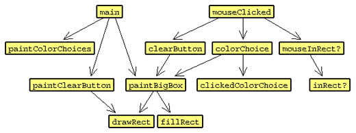 Figure 12.12
As an example of how to read this diagram, look at the main box. main invokes paintColorChoices, paintClearButtion, and paintBigBox. paintBigBox invokes drawRect and fillRect.
mouseClicked has a slightly more complex arrangement. Just in case you need a bit more help with the project, here is most of the body of my mouseClicked.
|
What's missing (where the "..." is) are a couple of inputs that my mouseInRect? is expecting. I gave you mouseInRect? so you should be able to figure out what I left out. But, this is my code - you might have taken or want to take a different approach. As you should know by now, there are many ways to solve a given problem...
All right, now you are on your own. Complete the project...
Looking Back
There are many ways to write this program and it is not obvious which approach is the best. In one year's rewrite of these notes [2007], I changed the structure of the solution described. Looking back, I've written this program a few times over the past ten-plus years. Each time, I think the new program is a bit more flexible and a bit easier to read.
As an example regarding flexibility, let's look at how easy it is to make a change to to the program. What if we were asked to change the size of the color choice boxes? I just checked. I changed the value of my colorChoiceSize symbolic constant - I changed 40 to 75. The program worked! The color choice strip was much bigger, almost twice as big; but everything worked just like the initial version of the program. This is nice... very nice.
So, why is this important?
Programs evolve. We will extend this program in a future lesson when we write a game called Mastermind. And, parts of programs you write can be copied into future programs you write. I can copy the drawRect, fillRect, and inRect? into future programs.
Summary
In this lesson, you learned
- about a new type of value, a boolean value. Boolean values are represented by the symbols (words) true or false
- about a new type of operator, a predicate, which outputs a boolean value. The predicates we used in this lesson compared two inputs for equality (the equal? operator) and compared the relative magnitudes of two inputs (the less? and greater? operators)
- about a new command if. With it you learned how to do things only when some condition is true
- about new boolean operators (and, or, not) which provide support for compound boolean expressions
- how to get the location of the turtle, the pos, xcor, and ycor operators.
Go to the Table of Contents
On to Recursion and Advanced Iteration
